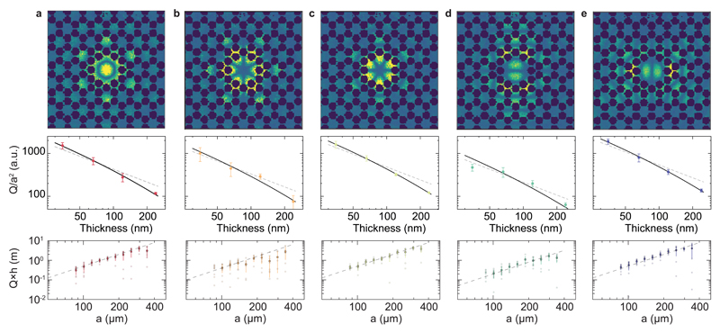
Fig. 3. Scaling of quality factors.
(a)-(e) Measured mode shapes of localised defect modes (top) with frequencies {fA, fB, fC, fD, fE} = {1.4627, 1.5667, 1.5697, 1.6397, 1.6432} MHz for a device with a = 160µm, as well as characteristic scalings with the membrane thickness h (middle row) and size, parametrized by the lattice constant a (bottom row), when either are varied. Dashed grey lines in the middle row indicate a Q/a2 ∝ h−1 scaling, while the solid black lines take into account the additional losses due to the bulk following eq. (5). Dashed grey line in bottom row indicates Q×h ∝ a2 scaling. The semi-transparent points correspond to the individual membranes, while the solid points (error bars) indicate their mean value (standard deviation).

