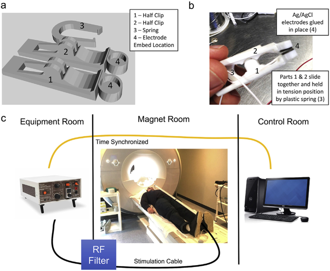
Fig. 3. taVNS/fMRI system overview.
a) picture of final taVNS electrodes that have been 3d printed and assembled b) CAD drawings of electrodes demonstrating the 3-piece design and “U” shaped spring clip. Ag/AgCl electrodes were affixed to the inside part of the electrode clips. c) Overview of how taVNS is synchronized and delivered to the participant in the fMRI scanner. Timing is driven from the console computer. Triggering of the direct current stimulator occurs in the equipment room which propagates an electrical stimulation current through a grounded RF filter and into the magnet room through a 10 m cable that attaches to the participant's ear in the scanner.

