
Figure 2.
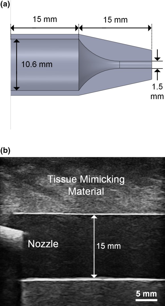
Overview of nozzle‐flow phantom. (a) Cross‐sectional view of the discharge nozzle showing the narrowing flow channel; (b) B‐mode image of the discharge nozzle inserted into a 15 mm diameter wall‐less PVA flow phantom (the interior of the discharge nozzle cannot be visualized due to acoustic shadowing of the fabrication material). [Color figure can be viewed at wileyonlinelibrary.com]