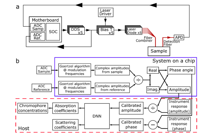
Fig. 1.
(a) Schematic diagram of the system. A system on a chip (SOC) drives 5 direct digital synthesis boards (DDS) to modulate 5 lasers which were combined and passed through a sample. An optical fiber collected the multiply scattered light, which was detected by an avalanche photo diode (APD). The APD signal was digitized by one channel of an analog to digital converter (ADC). The second channel of the ADC digitized a reference signal from the DDS boards. Each time the system was restarted, a measurement was taken on a calibration phantom (not shown) to calculate the instrument response. (b) Schematic diagram of the signal processing pathway. Items inside the blue box (solid line) were performed on the SOC. Items in the red box (dashed line) were performed on the host computer.

