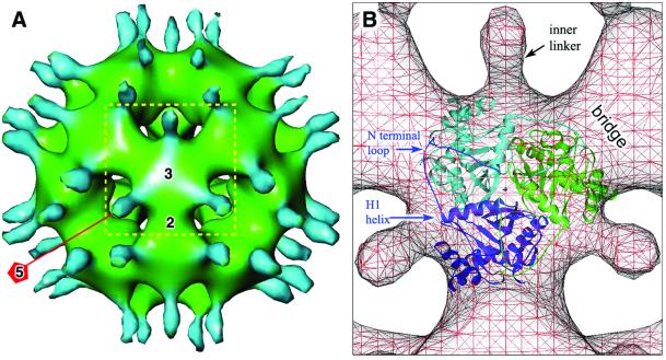
Figure 3.
Shaded-surface representations of 3-fold view of E2 core. (A) E1 was removed from PDC to reveal the underlying E2 core (green) and its inner linkers (light blue). An E2 trimer is outlined by the yellow square, and the 5-, 3-, and 2-fold axes are indicated. The linkers change the shape of the trimer base so that it appears that they are connected to its corners. (B) Superposition of the cut-away cryoEM PDC structure and the x-ray structure of B. stearothermophilus tE2. The atomic model of the tE2 dodecahedral core was directly superimposed on the core of the cryoEM structure by aligning the icosahedral 5-, 3-, and 2-fold axes with those of the cryoEM structure. For clarity, only one of the 20 tE2 trimers of the atomic model is shown. The dark and light blue and green x-ray ribbon structure represent the three identical subunits that comprise the tE2 core. The three N-terminal linkers are directly opposite the N-terminal helix (H1) near the middle of the outside edge of the trimer base as indicated, and the N-terminal loop is directed toward the 3-fold axis. The bridge interconnects adjacent trimers to form the dodecahedral core.

