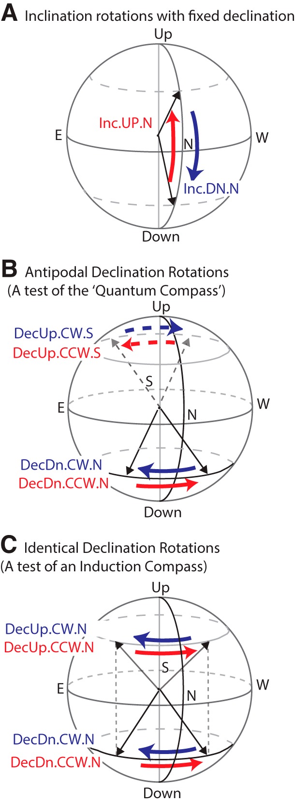
Figure 3.

Magnetic field rotations used in these experiments. In the first ∼100 ms of each experimental trial, the magnetic field vector was either: (1) rotated from the first preset orientation to the second (SWEEP), (2) rotated from the second preset orientation to the first (also SWEEP), or (3) left unchanged (FIXED). In all experimental trials, the field intensity was held constant at the ambient lab value (∼35 μT). For declination rotations, the horizontal rotation angle was +90° or –90°. For inclination rotations, the vertical rotation angle was either +120°/–120°, or +150°/–150°, depending on the particular inclination rotation experiment. A, Inclination rotations between ±60° and ±75°. The magnetic field vector rotates from downwards to upwards (Inc.UP.N, red) and vice versa (Inc.DN.N, blue), with declination steady at North (0°). B, Declination rotations used in main assay (solid arrows) and vector opposite rotations used to test the quantum compass hypothesis (dashed arrows). In the main assay, the magnetic field rotated between NE (45°) and NW (315°) with inclination held downwards (+60° or +75°) as in the Northern Hemisphere (DecDn.CW.N and DecDn.CCW.N); vector opposites with upwards inclination (−60° or −75°) and declination rotations between SE (135°) and SW (225°) are shown with dashed arrows (DecUp.CW.S and DecUp.CCW.S). C, Identical declination rotations, with static but opposite vertical components, used to test the electrical induction hypothesis. The magnetic field was shifted in the Northerly direction between NE (45°) and NW (315°) with inclination held downwards (+75°, DecDn.CW.N and DecDn.CCW.N) or upwards (−75°, DecUp.CW.S and DecUp.CCW.S). The two dotted vertical lines indicate that the rotations started at the same declination values. In both B, C, counterclockwise rotations (viewed from above) are shown in red, clockwise in blue.
