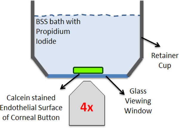
Figure 3:
Fluorescence imaging set-up. The retainer cup of the mechanical testing device, consisting of a stainless steel rim with a coverslip glass base, was placed on an inverted microscope to enable fluorescence imaging of the corneal endothelial surface. Cylindrical explants were laid endothelium-surface down inside the retainer cup. The endothelium was stained with calcein-AM to visualize live CECs in green, and submerged in a BSS bath containing PI in order to visualize injured/dead CECs in red. Three sets of multichannel fluorescence tiled images of the complete endothelial surface were obtained: 1) prior to mechanical indentation; 2) after mechanical indentation; and 3) after mechanical indentation but only at the site of indentation as an EFI projection to better visualize individual PI-labelled nuclei..

