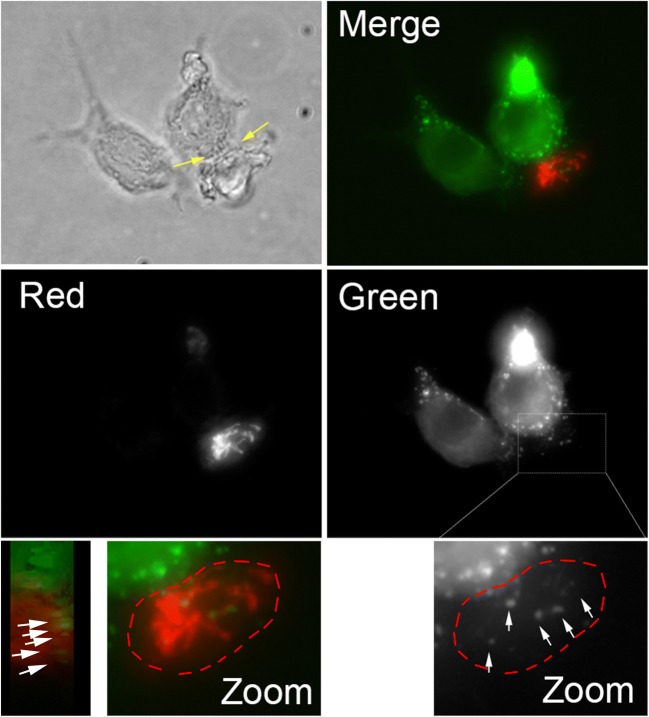
Fig. 3. TNTs observed between N5 and CEM-T4 are functional and allow for the transfer of Nef-GFP.
Representative image of the transfer of Nef-GFP between N5 (green) and CEM-T4 (red). Bright-field image showing short TNTs (yellow arrows) formed between N5 and CEM-T4, along with each individual channels and merge fluorescence images (z-projections) of N5 transfected with Nef-GFP mixed with CEM-T4 labeled with mitotracker red are shown. Nef-GFP aggregates (white arrows) are observed within the CEM-T4 acceptor cells (red) connected to the Nef-GFP transfected N5 via TNTs. Zoom-in of the merge CEM-T4 cell, along with a “side view”, shows that the Nef-GFP aggregates are within the CEM-T4 cells. A similar zoomed of the green channel is shown to better visualize the distinct Nef-GFP punctates observed within the red T cells. Transfer of Nef was only detected when CEM-T4 were connected to N5 via TNTs

