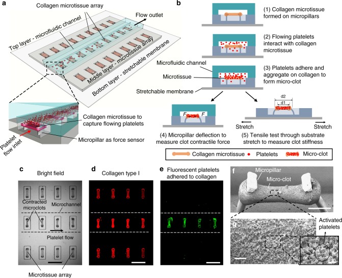
Fig. 1.
clotMAT system setup and microclot array formation under platelet flow. a clotMAT system contains a top microfluidic channel layer, a middle PDMS substrate containing the microtissue array and a bottom stretchable membrane. An array of exposed collagen microtissues capture flowing platelets to form individual microclots. b Schematic diagram shows microclot formation process and the principles of mechanical property measurement. Microclot contractile force is measured by micropillar deflection and stiffness is measured by substrate stretching-enabled tensile testing. A region of the microtissue array shown by bright field image (c), and immunofluorescence staining of the collagen (d) and adhered platelets (e) in the same region. Scale bar is 800 µm. Note that the platelet flow ran through the middle row of the collagen microtissue array, resulting in the adhesion of fluorescent-labeled platelets (green) only in this row. f SEM image of a microclot formed between the heads of a pair of micropillars. Obvious micropillar deflection is noticeable. Scale bar is 200 µm. g Zoom-in view of the microclot surface shows numerous platelets trapped in a fibrin meshwork. Scale bar is 10 µm. Inset shows activated single platelets. Scale bar is 2 µm. PDMS poly(dimethylsiloxane), SEM scanning electron microscopy

