Figure 3.
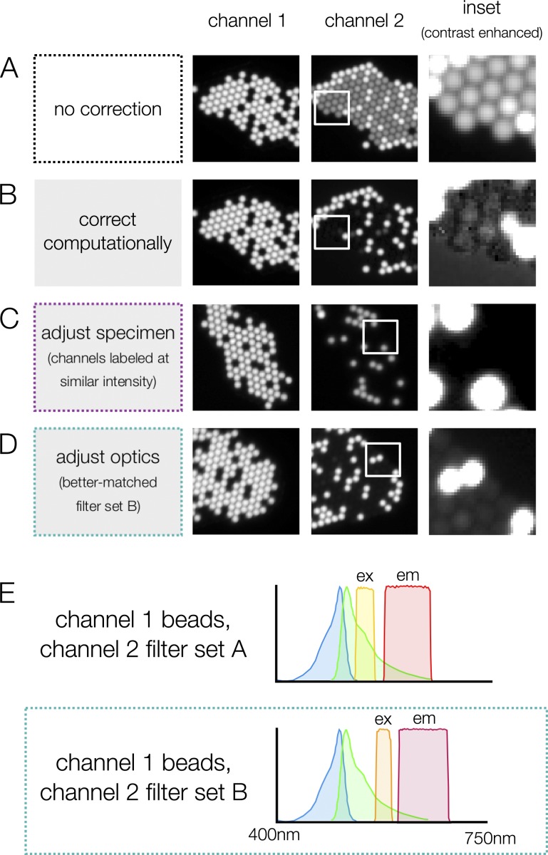
Image errors can be corrected in multiple ways. (A) Without correction, there is significant bleed-through from channel 1 into channel 2 (dimmer spots in channel 2 image). (B) Bleed-through can be corrected computationally (Fig. 2 C), but the correction can lead to artifacts that skew intensity measurements (see contrast-enhanced inset). Bleed-through can also be reduced by adjusting the specimen (C) or adjusting optics (D) in the microscope. Whether or not bleed-through is a problem for a particular experiment depends on the relative intensity of the fluorophores. In A, the beads in channel 1 are >300× brighter than the beads in channel 2; in C, beads of similar intensity are used, and bleed-through is no longer detectable. In D, a spectrally shifted filter set (E) is used to reduce bleed-through. At a glance, neither of these filter sets appears to have significant overlap with the excitation spectrum of the dye, but the small amount of overlap is exacerbated by the large difference in intensity between the channels.

