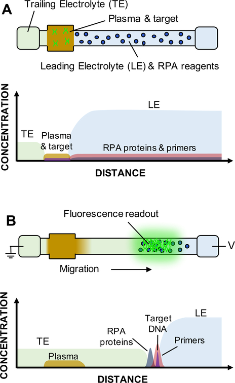
Figure 2.
Schematic of simultaneous ITP-RPA operation with filtered plasma. We show drawings of the glass fiber strip denoting locations of buffers, reagents, and sample, for the initial (A) and final (B) experimental time points. Approximate concentrations of each constituent are plotted with respect to distance. (A) Following passive filtration of the whole blood, plasma containing target DNA initially wets the sample pad on the left side of strip. LE and RPA reagents are disposed within the glass fiber membrane between the sample region and the LE reservoir. Pure LE and TE solutions reside in respective reservoirs. Initial spatial separation of reaction constituents prevents inhibitors in the sample from interacting with the amplification reagents. (B) Applying an electric field extracts DNA from the sample and focuses it with RPA reagents in the ITP plug. All constituents in the porous membrane electromigrate based on their respective charge and electrophoretic mobility. Nucleic acids and RPA proteins/enzymes speed past components of the plasma to focus at the interface of the LE and TE. The amplification reaction takes place within the concentrated ITP plug to create amplicons and detectable fluorescence.

