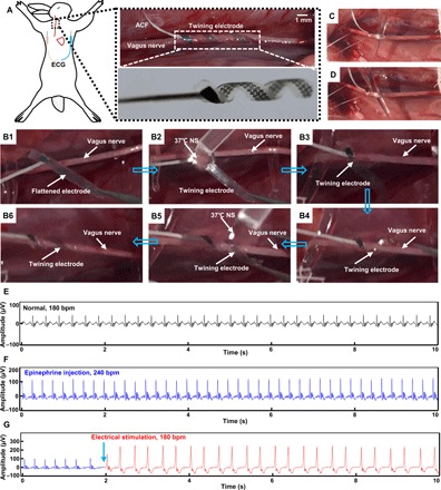
Fig. 5. Photographs and ECG data from the in vivo VNS animal experiments.

(A) Schematic diagram of VNS and recording of ECG (left) and images of an implanted twining electrode (inner diameter of 1 mm) on the vagus nerve (right). (B1 to B6) Images of the surgical implantation procedures of the twining electrode. (C and D) Illustrations of the twining electrode that conformally contacts the deforming vagus nerve. (E to G) ECGs of the anesthetized rabbit in a normal state (E), after epinephrine injection (F), and during electrical stimulation (G). Photo credit: Yingchao Zhang, Tsinghua University.
