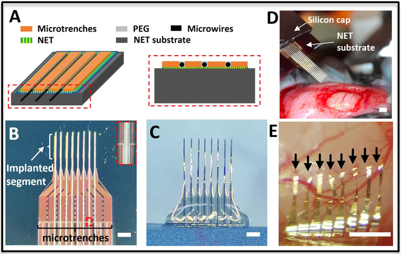
Figure 3:

Integrated microwire array and NET implantation. (A) Sketches showing the microfabricated trenches on top of the NET substrate (left) and the cross-sectional view (right). (B) Photograph of integrated microtrenches and microwires aligned on top of 8-shank NET probe on the substrate at the inter-shank spacing of 250 μm. Inset shows the zoom-in view of the dashed box. (C) Photographs showing the back side of assembled NET-microwire arrays after NETs were released from the substrate. (D) Photograph showing the stereotaxic insertion of the NET-microwire array. (E) Photograph of the implanted NET probe after microwires were retracted. The arrows point to the implantation sites of eight NETs at pitch of 150 μm. Scale bars: 500 μm.
