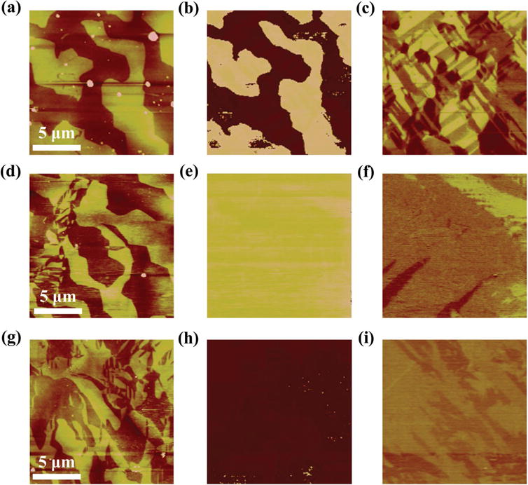
Figure 1.

PFM images of the as-grown (top), remanent states of the positively (middle), and negatively (bottom) polarized cases, respectively. The electric field was applied using the flexible conductive membrane method. Every row (from left to right) shows a,d,g) topography, b,e,h) OP-PFM images, and c,f,i) IP-PFM images.
