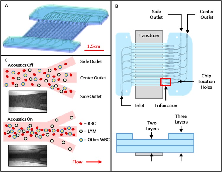
FIG. 1.
(a) Rendering of assembled 12-channel device with inlet at bottom left and outlets at top right. (b) Top and side views of device, showing channel layout, transducer position, and bonded layers. Layer thicknesses are exaggerated for clarity. (c) Illustration showing top view of idealized acoustic purification of lymphocytes from other blood cells as they exit the separation channel at its downstream end trifurcation. Insets are micrographs showing response of red blood cells (dark regions) at the outlet of a representative channel with transducer off and on.

