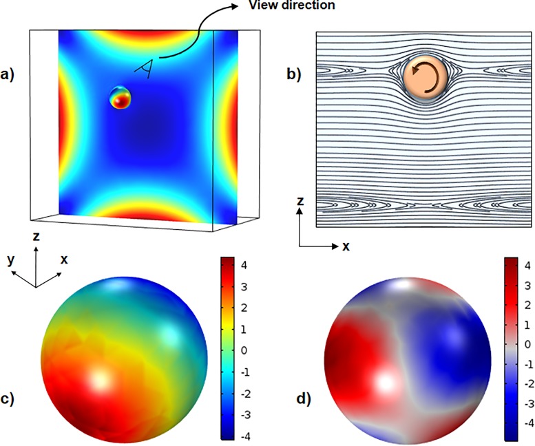
FIG. 4.
(a) Contour of first normal stress difference and pressure in the cross section of the channel and over the particle, respectively, for a flow rate of 25 μl/min. (b) Streamlines around the particle in the x-z symmetry plane. (c) Distribution of inertial stress on the surface of the particle. (d) Distribution of total elastic stress tensor.

