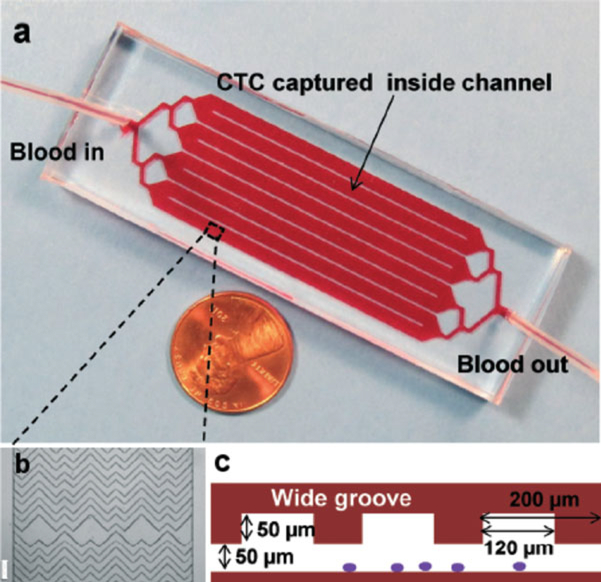
Fig. 1.
(a) The microfluidic chip, consisting of a single inlet that bifurcates into eight parallel channels that bifurcate into an outlet (each channel is 2.1 mm wide and 50 mm long). (b) Micrograph (4× magnification in bright field) of the staggered chevron grooves within a channel, showing their asymmetry and periodicity; scale bar = 200 μm. (c) Cross-sectional view of the grooves within the microchannels, with a channel depth of 50 μm and a groove depth of 50 μm; the groove pitch is 200 μm and the groove width is 120 μm. Adapted with permission from [6]

