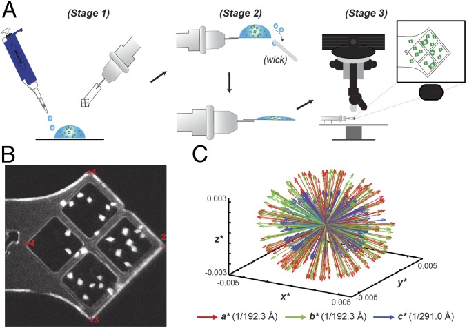
Fig. 1.
Loading and mapping of crystals on MCHs. (A) Schematic representation of MCH loading as detailed in Methods. (B) UV-microscopy image of Pol-Spt4/5 mounted crystals. Fiducial marks are indicated by a red asterisk. (C) Reciprocal space representation of the basis vectors of 221 indexed dGTPase images demonstrating the lack of preferential alignment when mounting in MCHs.

