
Figure 1.
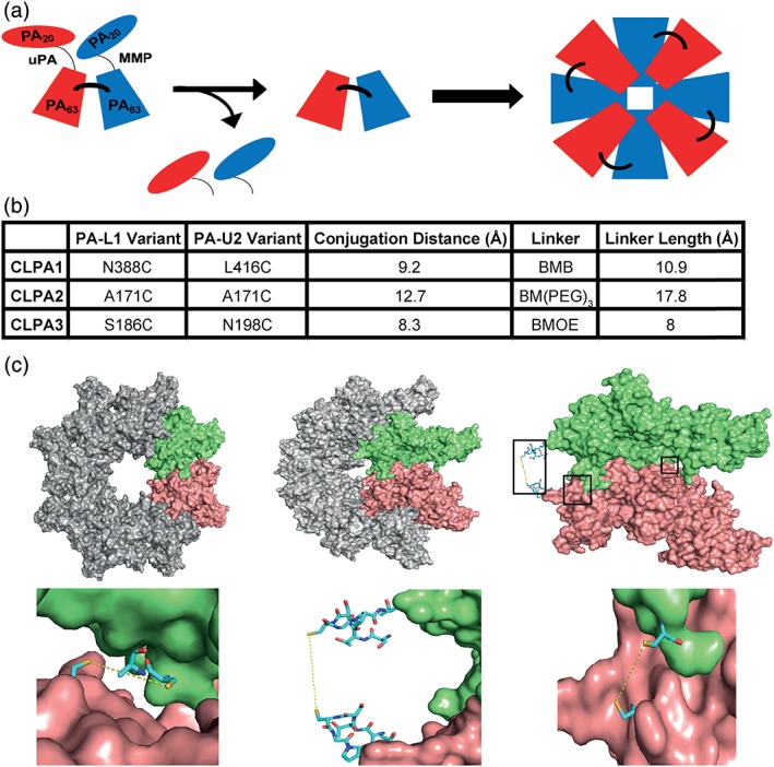
Cross‐linked PA tumor‐targeting agent design. (a) Schematic diagram of the CLPA tumor‐targeting system, which when activated by MMP and uPA proteases forms an octamer with cross‐linked PA components. (b) Table summarizing the three CLPA variants created and tested. The estimated distances between cysteine substitutions within each CLPA variant were calculated using the PyMol distance measurement tool. BMB = 1,4‐bismaleimidobutane, BMOE = bismaleimidoethane, and BM(PEG)3 = 1,11‐bismaleimido‐triethyleneglycol. (c) Illustrations of the PA cross‐linking interface, made using the crystal structure of the PA octamer (PDB ID: 3HVD) in PyMol. Each PA molecule is rendered as a surface, whereas important residues are rendered as stick models. Using O software,28 in adjacent PA monomers of the PA octamer crystal structure, single residues in PA‐L1 and PA‐U2 were substituted with a cysteine. Top left: PA octamer crystal structure with two adjacent PA monomers highlighted in lime and salmon. Top middle: PA octamer crystal structure rotated 45°. Top right: Two adjacent PA monomers within the rotated PA octamer are highlighted. The locations of the three PA cross‐linking sites are highlighted by black boxes to identify the areas expanded in the bottom three images. Bottom left: CLPA1 conjugation. Bottom middle: CLPA2. Bottom right: CLPA3.