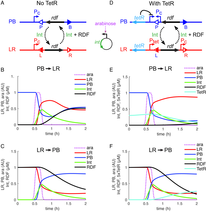
Figure 5.
Modelling of one-input switches. (A and D) Diagrams showing the genetic circuits for one-input switches without (A) or with (D) the TetR-based delay circuit. In (A), the RDF is expressed from a constitutively active promoter (Pc) only in the LR state. In (D), RDF is expressed from a TetR-repressed promoter (Ptet) in the LR state, and TetR is expressed from a constitutively active promoter (Pc) in the PB state. The input signal is provided by short pulses of arabinose that induce expression of integrase protein (Int) from a separate plasmid (shown between A and D). Int (with or without RDF) provides transitions between the PB (blue) and LR (red) states of the switch DNA. In (D), expression of TetR in the PB state delays RDF expression during the PB→LR transition. (B and C) Modelled kinetics of the PB→LR (B) and LR→PB (C) transitions for the switch without TetR. (E and F) Modelled kinetics of the PB→LR (E) and LR→PB (F) transitions for the switch with TetR controlled by the switch. Graphs show the relative amounts (arbitrary units; AU) of LR (red), PB (blue), arabinose (purple) and the concentrations (μM) of Int (green), RDF (black) and TetR (cyan). A single 12-min arabinose pulse was given at time point 0.5 h.

