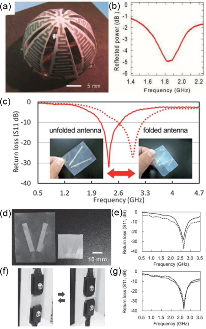
Figure 10.
(a–b) A 3D antenna based on paper substrate. (a) A picture showing the fabricated paper-based antenna patterned with a silver ink-contained ballpoint pen. (b) Measured reflected power confirms communication capability of the paper-based antenna. Reproduced with permission.[159] Copyright 2011, Wiley-VCH. (c) Return losses of paper-based foldable antennas can be tuned depending on how much the paper is folded. Solid line shows the return loss of an unfolded antenna and dotted line shows that of a folded antenna. Reproduced with permission.[160] Copyright 2013, The Royal Society of Chemistry. (d–g) A paper-based antenna for Wi-Fi communication. (d) Pictures showing a 30 mm long dipole antenna atop 50 μm thick nanopaper (left) and a 17 mm long dipole antenna atop 50 μm thick silver nanowire/nanopaper composite (right). (e) Return losses of the 30 mm long dipole antenna (solid line) and 17 mm long antenna on the silver nanowire/nanopaper composite (dashed line). (f) Pictures taken during bending of the nanopaper antenna and when it is restored. (g) The return loss of the nanopaper antenna before (solid line) and after (dashed line) 1,000 cycles of bending test. Reproduced with permission.[162] Copyright 2014, Wiley-VCH.

