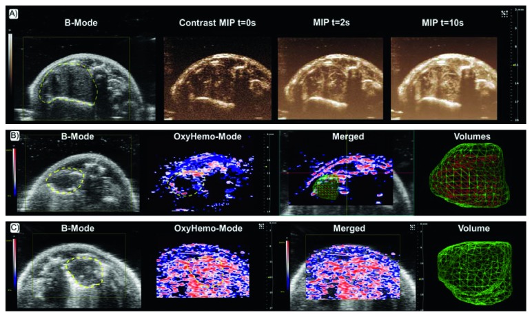
Figure 3.
PAI of tumor oxygenation. (a) B mode image of an orthotopic xenograft of lung cancer with corresponding maximum intensity projection (MIP) CEUS images at time points (t) 0, 2, and 10 s after microbubbles IV injection. (b) B mode image of a hypoxic lung tumor with corresponding oxygenation map (OxyHemo mode), showing red areas representing the oxygenated part, while blue and dark areas representing hypoxic parts of the tumor. In the following merged US-PA image, the 3D volumes of the whole tumor (green net) and of the hypoxic region of tumor (red net) are reconstructed. (c) Corresponding B mode, OxyHemo mode, merged US PA, and 3D volume images of a more oxygenated lung tumor without hypoxic core (reprinted with permission from Raes et al. [127], CC BY-NC-ND license, http://creativecommons.org/licenses/by-nc-nd/4.0/).

