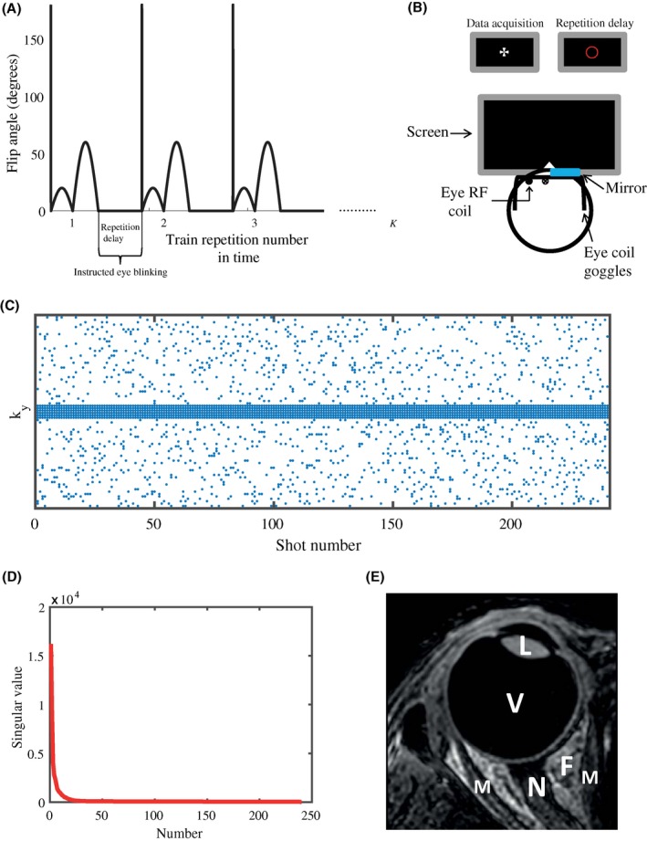
Figure 1.

The MRF sequence, instructed blinking set‐up, sampling pattern, and temporal correlation used in all experiments. A, Each flip angle train is preceded by an adiabatic 180° inversion pulse. The flip angle pattern consists of 240 RF pulses ranging from 0° to 60°. The total number of repetitions K of the MRF train is determined by the undersampling factor. The 2.5 s repetition delay between trains allows for instructed eye blinking when the scanner is not acquiring data. B, During data acquisition, a cross is shown on a screen placed at the end of the MR tunnel, which can be seen through 1 eye by means of a small mirror attached to the eye coil. During the repetition delay, the cross changes into a red circle, indicating that blinking is allowed before data acquisition starts again. The single loop eye coil setup is illustrated as well. C, Each time point (shot number) in the flip angle train is sampled differently. A simple variable density scheme is used. The outer region of k‐space is randomly sampled, whereas the central part of k‐space is fully sampled for each time point. The incoherent variable density sampling allows a CS reconstruction, while the fully sampled center can be used as calibration data for the MC‐based reconstruction. D, The singular values of the central k‐space/calibration matrix decay very quickly, which shows the low rank property of the eye MRF data, and forms the basis of the MC‐based reconstruction. Plots were generated for an undersampling factor of R = 12.3 in the outer region of k‐space, which results in a total undersampling factor of 6.7. E, Anatomical T1‐weighted 3D MR image of the eye, showing different ocular structures. L, lens nucleus; V, vitreous body; F, orbital fat; M, extraocular muscle; N, optic nerve
