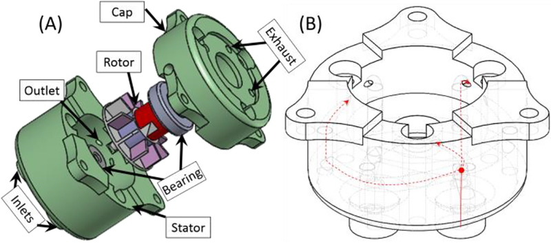
Fig.2.
(A) Exploded view of the motor assembly. The actuation unit includes stator, rotor, and cap. The rotor is supported by two plastic bearings to reduce friction, (B) Illustration of airflow channels inside the stator. The compressed air provided at the inlet (solid red line) is divided into three channels (dashed red line), which is terminated at the inner wall aiming the turbine blades. Motor rotation direction is reversed by changing the inlet to which the compressed air supplied.

