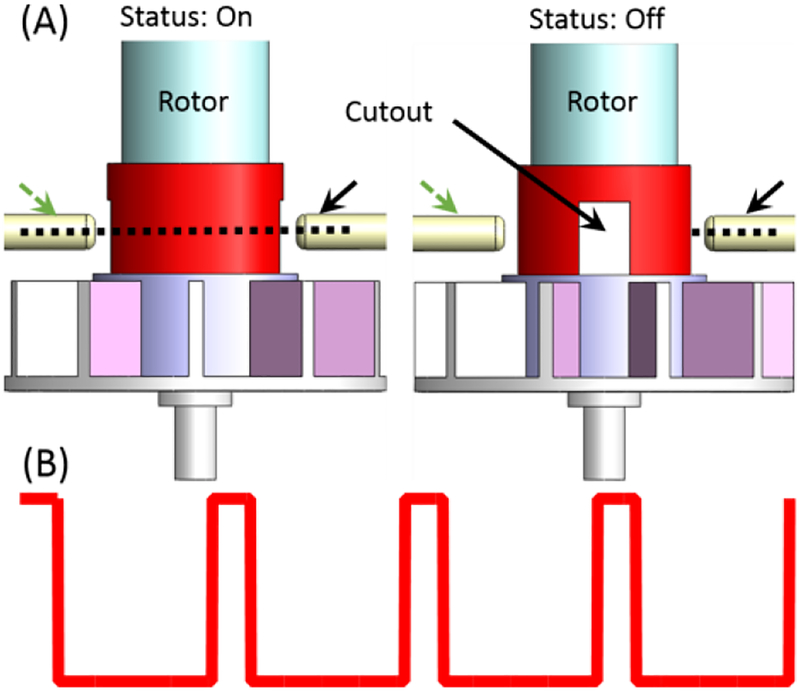
Fig.3.
Schematic diagram of the proposed binary optical encoding method. The cutout through the rotation axis of the rotor let the optical beam pass two times (i.e., two optical pulses) per revolution. The dashed and solid arrows indicate the receiver and sender optical fibers respectively. (A) Left: optical beam passing through the cutout, Right: optical beam interrupted by the rotor, (B) The signal detected at the receiving circuitry.

