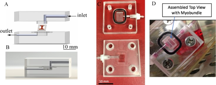
FIG. 1.
Custom perfusion system design and assembly. (a) Exploded view of the acrylic perfusion chamber housing the muscle bundle construct. Arrows denote the direction of flow. The final chamber volume is 80 μl after top fits within the bottom through a lock-and-key mechanism. The myobundle is attached to the porous nylon frame which rests on the bottom of the chamber. Fluid flows above and below the myobundle. (b) Side view of the chamber, showing the placement of the muscle bundle. (c) Photograph of upper and lower halves of the perfusion chamber, showing the 80 μl reservoir where the myobundle is located. (d) Photograph of the assembled chamber with the myobundle.

