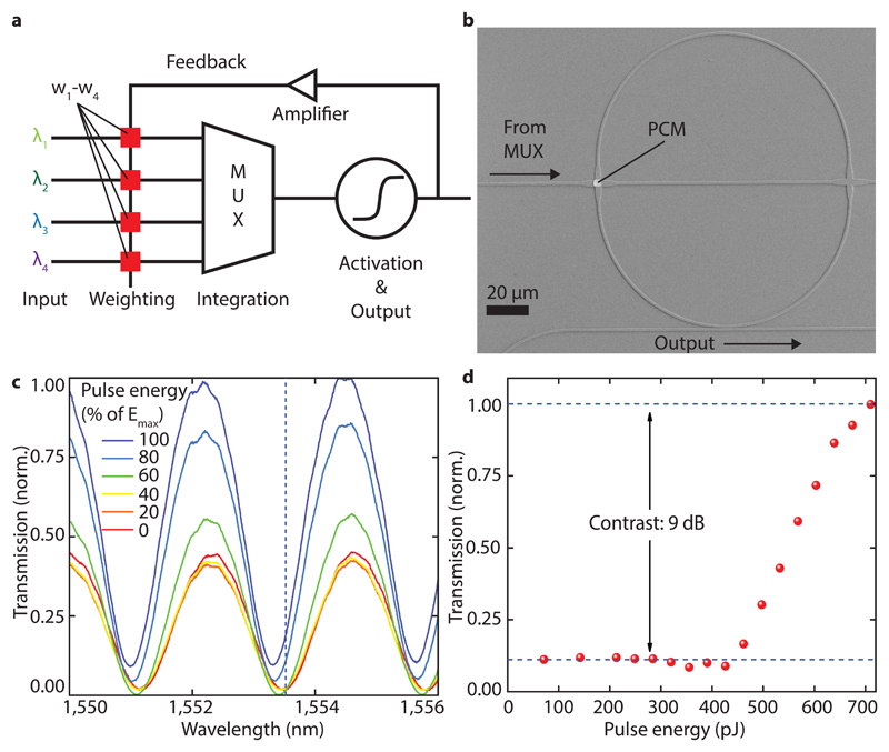
Figure 2. Spike generation and operation of the artificial neuron.
a) Schematic of the photonic implementation of a phase-change neuron circuit. Light of different wavelength is weighted by phase-change elements w1-w4 and summed up by a multiplexer to a single waveguide. If this activation energy surpasses a threshold, an output pulse is generated, and the weights are updated. b) Scanning electron micrograph of a ring resonator used to implement the activation function. By switching the PCM-cell on top of the waveguide crossing, the resonance condition of the resonator can be tuned. The waveguide on the bottom of the ring is used to probe the resonance and generate an output pulse. c) Transmission measurement of the device in b) and its dependence of pulse energy. The resonance shifts towards shorter wavelength with increasing pulse energy send to the PCM-cell on the ring. At the same time the transmission increases because of reduced absorption in the PCM-cell and thus changes the coupling between ring and waveguide. d) Normalized transmission to the output at a fixed wavelength (dashed line in c)) showing the activation function used to define the firing threshold of the neuron.

