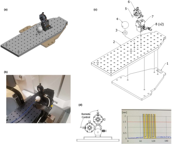
Figure 1.

A computer‐aided design model of the constructed phantom is shown in (a). A picture of the phantom mounted on the treatment machine is shown in (b). (c) An exploded‐view drawing of the phantom consisting of (1) an acrylic plate, (2) optical breadboard, (3) a acrylic spacer, (4) thermoplastic sphere, (5) infrared marker, (6) translation stage, (7) flipper motor, and (8) SubMiniature version A to Bayonet Neill–Concelman adapters. (d) An example IFMM trace during a treatment showing the IFMM marker distance (blue points) on the Y axis as a function of time in seconds on the X axis. The five interruptions due to the phantom motion signaled by the user are shown in yellow.
