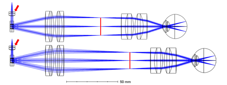
Fig. 1.
Schematics for a 4F (top) and our novel 5F (bottom) retinal OCT scanner design. The solid red lines denote the location of the intermediate image plane of the respective scanner. Red arrows denote the collimating lenses. The distance between the fiber tip and the collimating lens is increased in the 5F design to produce diverting light on the scanner.

