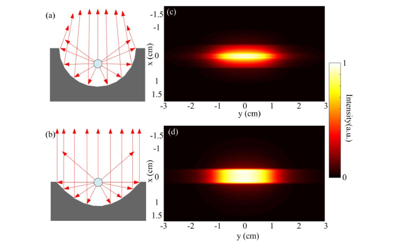
Fig. 4.
Comparison of the reflection pattern. (a) and (b) are the ray tracing for the circular cylindrical mirror and the parabolic cylindrical mirror, respectively. (c) and (d) are the simulated light distribution pattern at 5 mm away from the circular cylindrical mirror and the parabolic cylindrical mirror, respectively.

