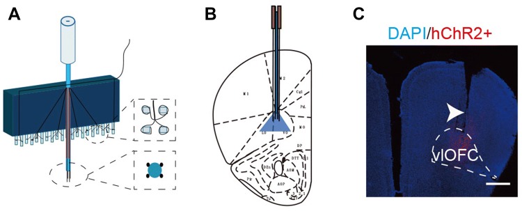
Fig. 3.
Fabrication of optogenetic probes and implant location. A Diagram of 16-channel optrode array. Each optrode contained an optical fiber for stimulation, and four tetrodes (16 channels) for electrical recording. B, C Location of optical stimulation and recording sites (arrowhead) in the vlOFC (scale bar, 750 μm).

