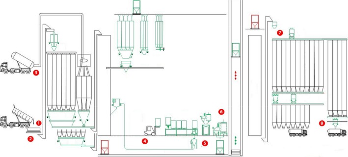
Figure 1.

General layout of a feed mill production system with highlighted sampling sites (adapted from http://www.kse.nl/en/alfra/). 1. Receiving ingredients pit gratin. 2. Receiving area. 3. Fat intake inlet. 4. Warehouse area. 5. Manufacturing area. 6. Pellet mill. 7. Load‐out auger. 8. Discharge bin boot
