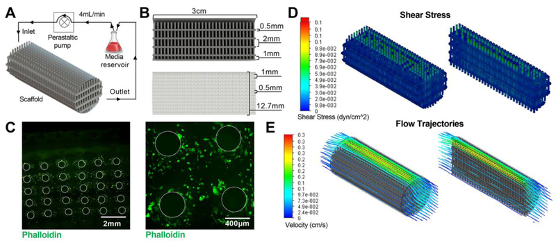
Figure 1. Bioreactor setup and scaffold characterization.
(A) Schematic representation of perfusion bioreactor setup. Scaffold seeded with HDMECs is connected to a peristaltic pump and media reservoir using tubing. Inlet and outlet of the media circulating at 4 mL/min flow rate are noted. (B) Cross-sectioned image of the scaffold generated in Solid Works showing dimensions of the scaffold as well as individual pillar height, diameter, and spacing. (C) Confocal images of the Phalloidin-stained scaffold seeded with HDMECs after 1 day of dynamic culture. Visual representation of varying levels of (D) shear stress and (E) flow trajectories at different areas within the scaffold as evaluated by computational flow simulation are shown.

