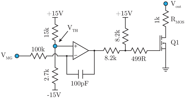
FIG. 2.
MOSFET “quench” circuit. When the mid-ground node VMG (also shown in Fig. 1) goes below the threshold value set at VTH, the op-amp puts the HV MOSFET Q1 into conduction. When engaged, the quench time constant is given by τ ≈ RMOSCout, which for our circuit is set to 1ms. The capacitor Cout = 1 μF is shown in Fig. 1, and details of this circuit are discussed in Sec. II C.

