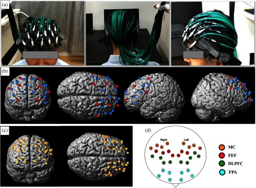
Fig. 2.
The configurations of optodes and channels. (a) The front, posterior, and left view of the optodes on a participant’s head. (b) The result of spatial registration of the optodes. Red squares denote the sources and blue squares denote the detectors. (c) The generated channels are labeled with numbers. (d) The anatomical labels of the channels. Dots with different colors represent different brain regions. Abbreviations: MC, premotor and supplementary motor cortex; FEF, frontal eye fields; DLPFC, dorsolateral prefrontal cortex; and FPA, frontopolar area.

