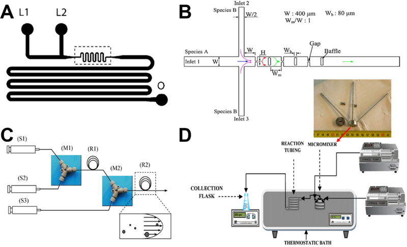
Figure 3.
Examples of laminar flow microreactors for the synthesis of solid silica sphere. (A) Schematic of microchannel has two liquid inlets (L1 and L2) and one outlet (O). Reproduced with permission from ref.39. (B) Schematic diagram of the baffled micromixer with three mixing units. Reproduced with permission from ref.45. (C) Schematic diagram of microreactor system for silica synthesis. (S1), (S2), and (S3) are syringe for TMOS, HCl, and PEI polymer in Tris-HCl buffer solution, respectively. (M1) and (M2) are Y-shaped mixers. (R1) is the reaction tube for hydrolysis, (R2) is the reaction tube for silica precipitation. Reproduced with permission from ref.46. (D) Experimental setup using standard slit interdigital micromixer for the continuous silica particle synthesis. Reproduced with permission from ref.44.

