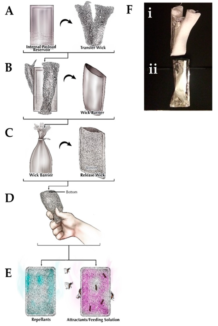
Figure 1.
Controlled-release device. The (A) internal payload reservoir is surrounded by the transfer wick and they are placed together inside the (B) wick barrier. This wick barrier is placed inside the (C) release wick before being (D) utilized to (E) release either repellants or attractants/feeding solutions. (F) Actual images of the (i) internal reservoir and transfer wick that is inserted into the (ii) wick barrier.

