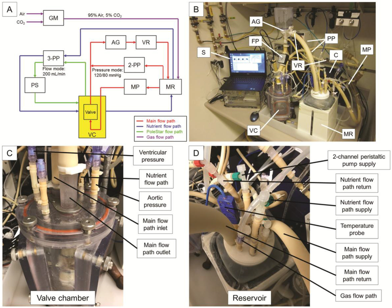
Figure 1. Bioreactor system schematics.
(A) Schematic and (B-D) photographs of the bioreactor system showing critical components. The main flow path (red) utilizes the main pulsatile pump to generate flow through the valve lumen and additional components to achieve desired pressures above and below the valve throughout the cardiac cycle. The nutrient flow path (blue) circulates medium between the heated and oxygenated reservoir and the valve chamber. The PoleStar flow path (green) samples medium from the valve chamber to monitor pO2, pCO2, and pH. The gas flow path (purple) introduces a mixture of 95% air and 5% CO2 to the medium reservoir. Abbreviations: AG - afterload generator, C - controller, FP - flow probe, GM - gas mixer, MP - main pulsatile pump, MR - medium reservoir, 2-PP - 2-channel peristaltic pump, 3-PP - 3-channel peristaltic pump, PS - PoleStar optical process monitor, S -software, VC - valve chamber, VR - variable resistor.

