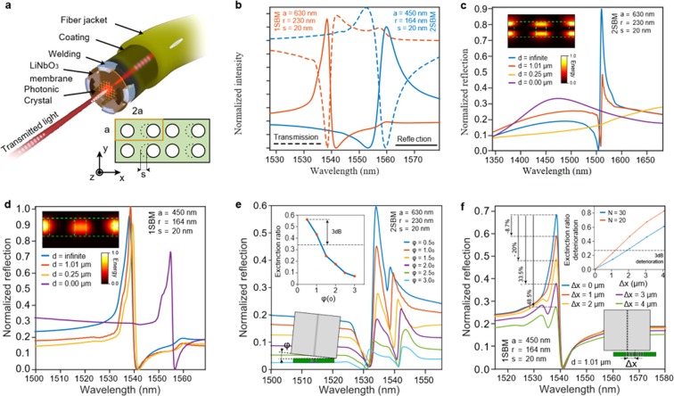
Figure 1.
Sketch and numerical analysis of the fiber tip sensor. (a) Rendered image of the PCS attached to the fiber extremity (top) Geometry of the photonic crystal (bottom). (b) Transmission and reflection spectra for both 1SBM and 2SBM operating structures. (c,d) Computed reflection spectra in function of the air/gap length between the fiber section and the PCS for both (c) 2SBM and (d) 1SBM. In the inset, its respective electric field distributions. (e,f) Tolerance analysis to (e) the unacuraccy on the parallelism between the fiber section and the PCS and (f) the miss-centering error.

