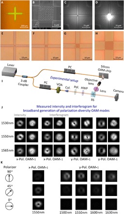
Fig. 4. Fabricated devices, experimental setup, and measured results for the generation of broadband polarization diversity OAM modes.

(A) Measured optical microscope image of the layout of superposed holographic fork gratings connected by four adiabatic tapers. (B) Measured SEM image of the superposed holographic fork grating region. (C) Measured optical microscope image of the device without incidence of the in-plane guided mode. (D) Measured near-field view (bright spot from the center grating region) for generating y-pol. OAM−1 with incidence of the in-plane guided mode. (E to H) Measured optical microscope images of the fabricated devices with different lengths of the grating region of 2.4 μm (E), 3.6 μm (F), 5 μm (G), and 10 μm (H). (I) Experimental setup. PC, polarization controller; VOA, variable optical attenuator; Col., collimator; Pol., polarizer; HWP, half-wave plate; BS, beam splitter. (J) Measured far-field intensity profiles and interferograms for the broadband generation of polarization diversity OAM modes (x-pol. OAM+1, x-pol. OAM−1, y-pol. OAM+1, y-pol. OAM−1) in the C-band. (K) Measured far-field intensity profiles of x-pol. OAM+1 (1550 nm) and y-pol. OAM+1 (1500, 1550, 1600, 1630 nm) after a rotating polarizer (90°, 45°, 0°).
