Figure 2.
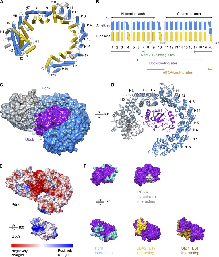
Structure of the Pdr6•Ubc9 import complex and overview of Pdr6 secondary structure. (A) Pdr6 in the import complex is shown. A and B helices of the HEAT repeats are represented as cylinders and shown in blue and yellow, respectively. (B) Schematic representation of the Pdr6 secondary structure. Coloring is the same as in A. Tilted cylinders represent interruptions in the right-handed arrangement of successive HEAT repeats. Green, purple, and orange lines below the cylinders indicate repeats that interact with RanGTP, Ubc9, and eIF5A, respectively. (C and D) View of the complex in two different orientations. (C) The import complex is shown as the surface representation. Pdr6 is depicted with a color gradient from gray (N-terminus) to blue (C-terminus) while Ubc9 is shown in purple. (D) The complex is rendered as a ribbon representation. The secondary structure of interacting Pdr6 and Ubc9 regions are labeled. (E) Pdr6 and Ubc9 surfaces are shaded according to electrostatic potential with a color gradient from red (negatively charged, −10 kcal/mol) to blue (positively charged, +10 kcal/mol). Pdr6 is shown in the same orientation as in C while Ubc9 is rotated 180°. (F) Ubc9 is rendered as a surface representation, shaded in purple and shown in two orientations. Interaction interfaces of Ubc9 are marked in cyan (Pdr6 contacts), yellow (UBA2 contacts, PDB 3ONG), brown (SIZ1 contacts, PDB 5JNW), or gray (PCNA contacts, PDB 5JNE).

