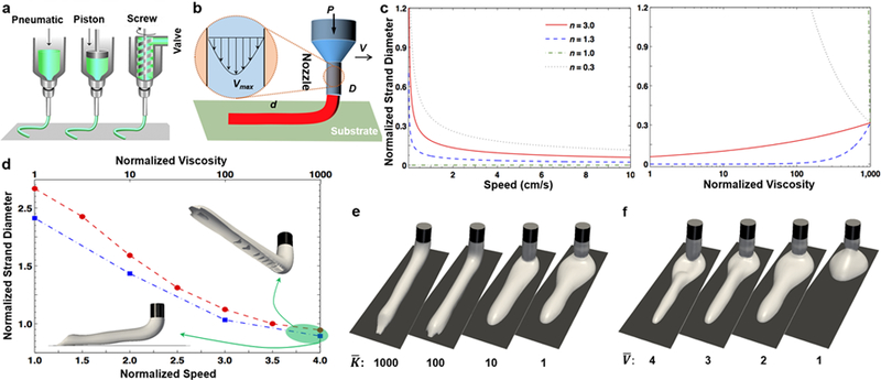
Figure 3.

a) An overview of the most common extrusion bioprinting approaches; reprinted with permission from Malda et al. 201377. b) Schematic of the theoretical modeling, with an inset showing a realistic velocity profile inside the nozzle. c) Theoretical simulation of normalized strand diameter (d/D) versus normalized viscosity (: K divided by water viscosity) and theoretical simulation of normalized strand diameter (d/D) versus nozzle moving speed (V) for four power-law constant values. d) Numerical simulation of normalized strand diameter (d/D) versus normalized speed (= V divided by inlet velocity of bioink ~ Vmax/2; for n=0.3 and =100; circle; red) and normalized viscosity (for n=0.3 and =3; square; blue), where 3D perspectives of extruded bioinks are shown for the extreme case. e) 3D perspective view of bioink extruded for four viscosity ratios () and n=0.3. f) 3D perspective view of bioink extruded for four velocity ratios () and n=0.3.
