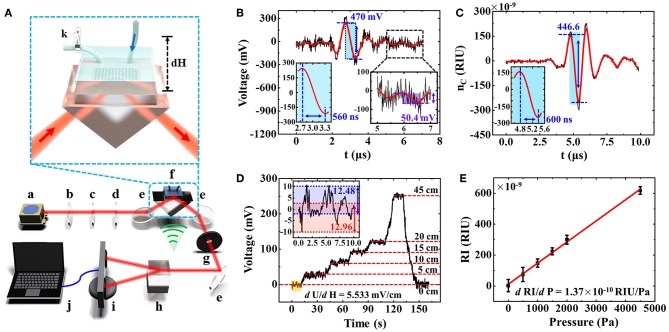
Figure 4.
(A) Experimental setup schematic of rGO-based microfluidic sensor. a, laser; b, attenuator; c, polarizer; d, 1/4 wave plate; e, reflecting mirror; f, rGO-glass-based microfluidic chip device; g, aperture; h, Wollaston prism; i, balanced detector; j, computer; k, ball valve. (B) The direct detection of a weak RI change of water solution generated by an ultrasonic wave. (C) The optimized RI change detection of water. (D) The relationship between voltage signals and the liquid level. (E) The detected RI change as a function of water pressure in the detection window, which is caused by liquid level difference.

