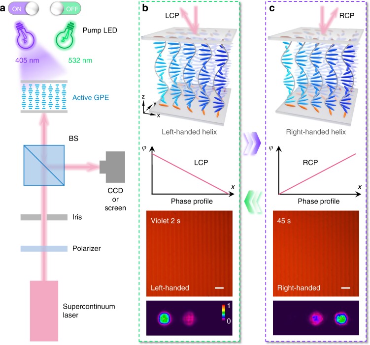
Fig. 3.
Light-activated beam steering. a The optical setup for characterizing active CLC GPEs. CCD, charge-coupled device; BS, non-polarizing beam splitter; GPE, geometric phase element. b, c Schematic illustrations, theoretical phase profiles, micrographs and reflected diffraction patterns (λin = 650 nm) of the dynamic CLC deflector under (b) 2 s and (c) 45 s violet light irradiation. The CLC directors on the substrates are highlighted in orange. Note that this system can be reversibly driven by irradiation with green light. Both scale bars are 100 μm. The color bar indicates the relative optical intensity

