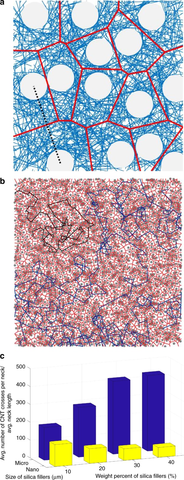
Fig. 7.

Voronoi tessellations (represented in red solid lines). Voronoi geometries are constructed based on center points of silica fillers (gray circles) a with a diameter of 4 μm and b with a diameter of 20 nm over the 2D model illustrated in Supplementary Fig. 10(b) and (d), respectively. A straight line connecting the center points of the two nearest silica fillers (represented in black dashed line in a) in the normal direction of a red conducting path (the side of a Voronoi tessellation) is associated with a neck in the 2D model. c Average number of CNT crosses per neck/average neck length for micro- and nano-silica composites with respect to silica contents
