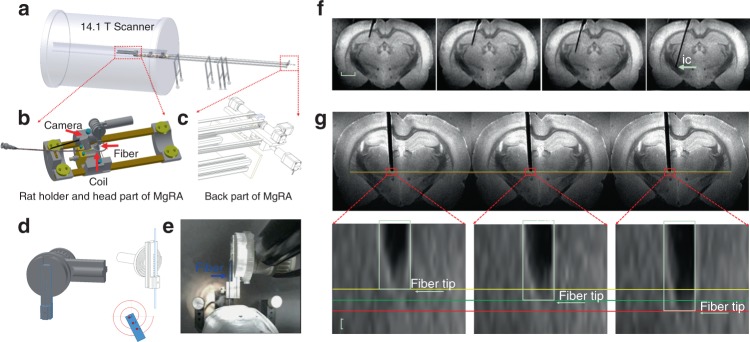
Fig. 1.
3D view of the MgRA and its application in ex vivo studies. a Overview of the MgRA inside the 14.1 T MR scanner. b Schematic of the customized animal holder and head part of the MgRA. Both MR compatible camera and surface transceiver coil are included for monitoring the fiber optic insertion inside the MR scanner. c Stepper motors implemented at the back part of the MgRA to control up to four degrees-of-freedom movement. The long arm reaching 4.7 m away from the magnetic center point excludes the influence by the ultra-high magnetic field. d Schematic drawing of the Archimedean spiral design to transmit the dorsal–ventral movement. e Snapshot of the mechanically controlled fiber optic movement videotaped by the built-in camera. f Time-lapsed images showing the optical fiber targeting the hippocampus, thalamus, and internal capsule along the insertion trajectory. Scale bar, 2 mm. g Three continuous MRI anatomical images with step distance 50 µm (the MRI in-plane resolution is 50 × 50 µm2, thus it can be seen that the distance moved in each step is approximately 50 µm). Scale bar, 50 µm

