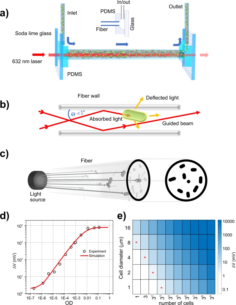
Fig 1. RUSD.
(a) Optical schematics of the RUSD apparatus, which utilizes the high reflectance coefficient of light at the interface between thin and dense media (water and glass) at high incidence angles. (b) The focal distance of the laser is set such that the incidence angle (θ) of the laser at the fiber wall remains > 89°. At θ > 89°, the reflectance coefficient of laser light is R > 0.82 for both s and p polarizations of light, allowing the laser beam to travel in liquid and reflect multiple times within the fiber. (c) During travel, any photon encountering a cell or a particle is either absorbed or scattered, losing the angular condition to be guided by the fiber (i.e., θ > 89o), and any cell on the light path reduces the total intensity proportional to its cross-sectional area and creates a 2D shadow-projection image on the optical detector. The current from the reverse-biased optical detector is passed through a resistor in which the potential difference is converted to a signal for data acquisition. (d) The voltage signal as a function of cell density. Simulation data based on the mathematical model described here and actual RUSD exhibit a high degree of concordance (R2 = 0.97) up to OD > 10−3 and (R2 = 0.93) for the whole data range used here. (e) Signal strength versus number of cells and cell dimensions in RUSD: As the cell size increases, signal strength is multiplied proportionally to the cell cross-sectional area. The cell shape is taken as a square pattern with the specified dimensions. The region marked with red asterisks indicates the boundary of detection at which the signal is above the 1 mV limit. RUSD signal rapidly saturates over approximately OD 0.1 as cells optically block the fiber cross section. OD, optical density; PDMS, polydimethylsiloxane; RUSD, rapid ultrasensitive detector.

