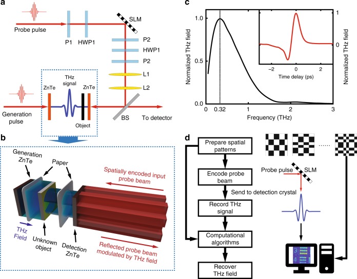
Fig. 1. Experimental Configuration.
a Schematic of the system configuration. b A detailed description of our sampling approach. The unknown object, an AF test chart, is wrapped in paper so that it is invisible to the NIR probe beam. P1, P2, and P3 are polarizers, while HWP1 and HWP2 represent half-wave plates. L1 and L2 image the SLM plane onto the left surface of the ZnTe detection crystal. BS is a 50/50 beam splitter. The probe beam, whose polarization has already been modulated, is then sent to a single-pixel detector for measurement. Detailed specifications can be found in the Methods section. c The spectrum of the generated THz pulse, and the time-domain electric field distribution with a spatial mask encoded on the NIR probe beam. The spectral peak occurs at 0.32 THz, which corresponds to a central wavelength of 940 μm. The SNR of the THz signal is ~300. d The flowchart shows our procedure for single-pixel imaging via probe-beam encoding

