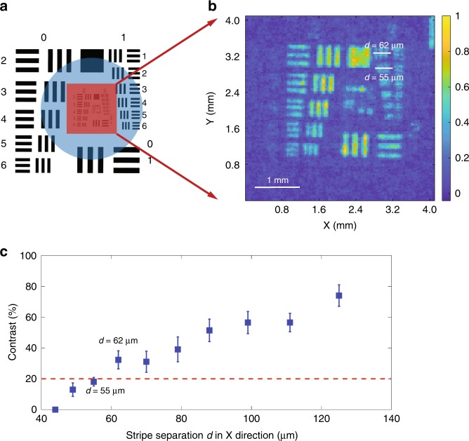
Fig. 2. Resolution Estimation.
a The original AF target. The red square indicates the area that the probe beam illuminates. The blue circle shows the parts illuminated by the THz field. By changing the location of the encoding masks on the SLM, we can probe any part of the THz field in the blue circle without changing the optics. b The experimental result with 128 × 128 pixels showing the resolution limit, which is the recovered image of the red square part in a. c The contrast as a function of strip separation d. The red dashed line is the threshold contrast assumed by the Rayleigh criterion. Two points can be resolved if the contrast is equal to or >20%. Therefore, the element set with d = 55 μm is not resolved while the element set with d = 62 μm is resolved according to the Rayleigh criterion. The intensity cross sections of element sets 3–1 and 3–2 can be found in the Fig. S1 in the Supplementary Information

