Fig. 4.
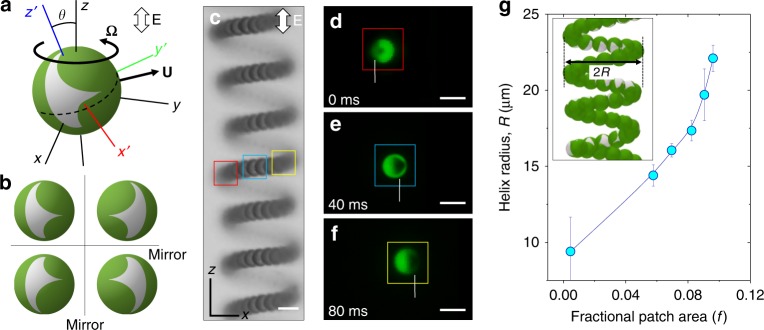
Patch orientation and effect of its size on helical motion. a Schematic showing the reference frames and velocity (angular and linear) vectors of a particle aligned at an oblique angle (θ) with the axis of the applied field (z-axis). b Schematics of the four degenerate states of a particle with a triangular patch in uniform AC-electric field. The four stable orientations result in the four distinct helical trajectories of the particle. c Superimposed bright-field micrographs of a patchy particle migrating along cylindrical helical trajectory in an AC-electric field of strength 250 V cm−1 and frequency 10 kHz. d–f Fluorescence micrographs of the particle with a triangular metal patch performing helical motion. Here the color of the boxes corresponds to the location of the particle along its helical path as shown in c (Supplementary Movie 3). Scale bars shown in c–f are 5 µm. g Increase in the radius of the helical trajectory with increasing size of the triangular metal patch at constant electric field of 325 V cm−1 and frequency 10 kHz and particle radius a = 2.6 μm. The error bars in g refer to the standard deviation of the data set of at least ten measurements

